[](https://www.pinballnews.com/site/wp-content/uploads/learn/pinball-add-on-controller/001-pinball-add-on-controller.jpg)
Pinball News is all the news about pinball – you need to scope it out
**Purpose**
This article is the second part of a two part [Pinball News Learn How](https://www.pinballnews.com/learn/) set of articles. This second half concentrates on software, whereas the [first half](https://www.pinballnews.com/site/?p=27423) focused on hardware.
This set is a continuing update to a previous set ([first](https://www.pinballnews.com/site/2017/01/11/intro-to-arduino/) and [second](https://www.pinballnews.com/site/2017/01/12/pin-uino/)) of article halves. The subject of all four of these articles is the use of [AVR RISC Microcontrollers](https://en.wikipedia.org/wiki/AVR_microcontrollers) with pinball machines.
The purpose of this article pair is to provide general information and tips for creating your own AVR microcontroller based pinball add-ons, such as an interactive topper.
Though one specific pinball topper is covered in this half, it is only included for the purpose of bringing together software examples from this half and hardware examples from [the previous half](https://www.pinballnews.com/site/?p=27423). Together, these two halves combine show one completed project.
**Introduction**
This second article deals with the use of Arduino software.
It starts with an explanation and a few simple Arduino sketches for *Digispark* clone boards. It them moves on to a more complicated programming example, requiring multiple inputs to control multiple outputs, and the use of a *Nano* clone board.
For information on running and using the Arduino IDE software to write and upload your sketches, see the [previous article about the Digispark-based IR testers](https://www.pinballnews.com/site/2022/10/16/new-ir-pinball-testers-part-two/).
As previously stated, the completed hardware and software project is shown in this half. Links for going further are also included towards the end of this article.
**Information**
Because the *Digispark* clone board is smaller and simpler than a *Nano* clone board, we will start by considering the *Digispark*. Its postage stamp size makes it ideal for easily hiding in a pinball topper or, when used for the addition of a custom playfield feature, finding space to mount it under the playfield.
Due to it being ATtiny85 microcontroller based, this board only has enough power and resources for a single lighting effect or single user-created feature. For larger, more complicated projects, a *Nano* clone board can be used instead. This board has greater storage for your sketch and can more easily use multiple inputs to control multiple outputs.
This article will actually make two updates:
* We will update from the use of a single microcontroller; by adding **I**nput/**O**utput (**I**/**O**) modules.
* We will also modernize from ‘dumb’ discrete LEDs to ‘smart’ LED modules called *[NeoPixels](https://learn.adafruit.com/adafruit-neopixel-uberguide/form-factors)*.
In a previous Pinball News article about updating the use of all discrete electronic components to an ATtiny85 microcontroller based board, we recommended to readers that they take the time to read and understand an associated [user guide](http://digistump.com/wiki/digispark/tutorials/connecting) for that board. The same holds true for this article. We recommend you take the time to read and understand the *[Adafruit NeoPixel Überguide](https://learn.adafruit.com/adafruit-neopixel-uberguide)*, by Phillip Burgess.
The two important take-aways from the *NeoPixel Überguide* are:
* *NeoPixels* require some RAM from the host microcontroller. This is a consideration for larger projects than in this article, in which case an *Arduino* or *Arduino* clone microcontroller board with greater RAM might need to be utilized.
* Each *NeoPixel* works on positive five volts (+5V) and draws as much as sixty milliamps (60mA) of direct current (dc). The use of more than a few *NeoPixels* can require more power than your board’s built-in voltage regulator can provide.
Five things to remember while programming NeoPixels:
* This type of LED has three dies: red, green & blue
* The dies are used together in additive lighting to create millions of colors
* The die order many not be the same for all *NeoPixel* or *NeoPixel*-like LEDs and must be properly set-up for the additive lighting effect to work correctly
* Your sketch must include the [Adafruit\_NeoPixel.h](https://github.com/adafruit/Adafruit_NeoPixel) [library](https://learn.adafruit.com/adafruit-neopixel-uberguide/arduino-library-use): **#include <Adafruit\_NeoPixel.h>**
* *NeoPixels* are declared as an object. That object has three arguments: (LED\_COUNT, LED\_PIN, and NEO\_Type)
Lastly, you should set the initial state of the *NeoPixels* at the beginning of your sketch. An example follows:
```
void setup() { strip.begin(); // Prepare the data pin for NeoPixel
strip.show(); // Initialize all pixels to 'off'
}
```
**Digital Input to Control an Output**
We will start with some building blocks.
The first is one of the more easy and simple ways: one input, an *Arduino*-based microcontroller, a sketch and a single LED as the output.
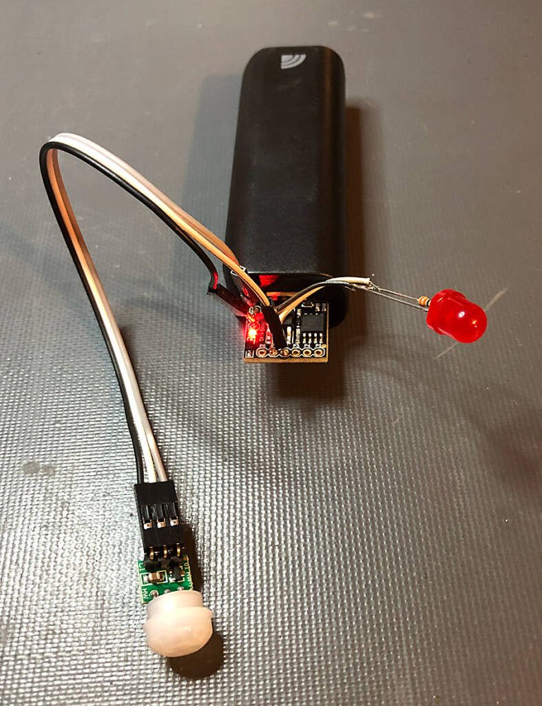
Pictured juxtaposed below: the digital output of a passive infrared receiver (PIR) is used to supply a toggling signal to a *Digispark* microcontroller clone board, which in turn illuminates a single red LED on the high toggle.
[](https://www.pinballnews.com/site/wp-content/uploads/learn/pinball-add-on-controller/002-pinball-add-on-controller.jpg)
A PIR sensor input, the *Digispark* clone, the LED output and a 5V battery pack
From looking at the associated sketch (HC-SR505PirRSensorTest.INO – shown below and [downloadable here](https://pinballnews.com/site/wp-content/uploads/learn/pinball-add-on-controller/HC-SR505PirRSensorTest.INO.ino)), you may notice the [digital](https://www.arduino.cc/reference/en/language/functions/digital-io/digitalread/) HIGH and LOW states of the input module trigger a state change of the microcontroller [output](https://www.arduino.cc/reference/en/language/functions/digital-io/digitalwrite/); from OFF to ON:
```
val = digitalRead (pirPin); // Read input value (active HIGH)
if (val == HIGH) // Check if input is HIGH
digitalWrite(alarmLED, HIGH); // Turn LED ON
else {digitalWrite(alarmLED, LOW);} // Turn LED OFF
```
[](https://www.pinballnews.com/site/wp-content/uploads/learn/pinball-add-on-controller/003-pinball-add-on-controller.jpg)
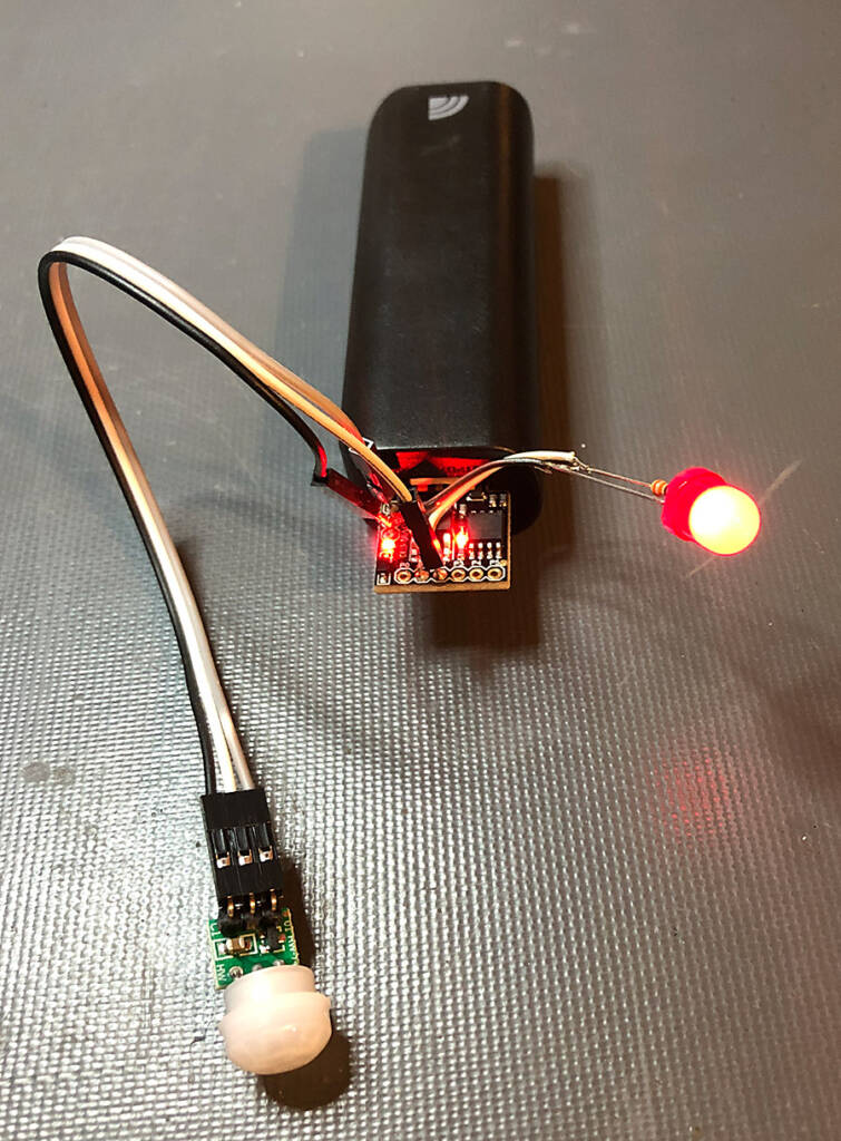
When motion is detected the input goes high and the Digispark sets the output high to light the LED
Look at the tiny red surface-mount LEDs on the *Digispark* clone board and the large output LED. In both pictures, notice the power indicator LED on the *Digispark* clone board remains constantly lit.
In the first picture, notice how both the *Digispark* clone’s on-board red LED and the red output LED are unlit. In the second picture, notice how both the on-board and output red LEDs are glowing. This was after the [**PIR**](https://learn.adafruit.com/pir-passive-infrared-proximity-motion-sensor) module was triggered. When the PIR module resets, the output LED turns off. This cycle continues as the PIR module gets re-triggered and resets itself.
The Arduino sketch for the example above follows. It is commented to list all of the connections and the operation of the sketch itself. You can also [download it here](https://pinballnews.com/site/wp-content/uploads/learn/pinball-add-on-controller/HC-SR505PirRSensorTest.ino).
```
// HC-SR505PirRSensorTest.ino
/* Pinball News
* https://www.pinballnews.com/site/
* 09-OCT-22\\
* This sketch is intended for public use.
*/
int alarmLED = 1; // Output pin # for the LED
int pirPin = 2; // Input pin # on Arduino from PIR sensor (active HIGH)
int pirState = LOW; // Assuming no motion detected
int val = 0; // Variable for reading pin status
int flashCount = 3; // Variable for number of alarmLED flashes
int flash = 33; // variable time for flashing the LED
void setup() {
pinMode(alarmLED, OUTPUT); // declare LED as output
pinMode(pirPin, INPUT); // declare sensor as input
for (int k = 0; k < (flashCount + flashCount); k++) { // Flash quick setup verification sequence
if (k % 2 == 0) {
digitalWrite(alarmLED, HIGH);
}
else {
digitalWrite(alarmLED, LOW);
}
delay(flash);
}
}
void loop() {
val = digitalRead (pirPin); // Read input value (active HIGH)
if (val == HIGH) // Check if input is HIGH
digitalWrite(alarmLED, HIGH); // Turn LED ON
else {digitalWrite(alarmLED, LOW);} // Turn LED OFF
}
```
**Analog Input to Control an Output**
Next we will move on to a slightly more complex building block.
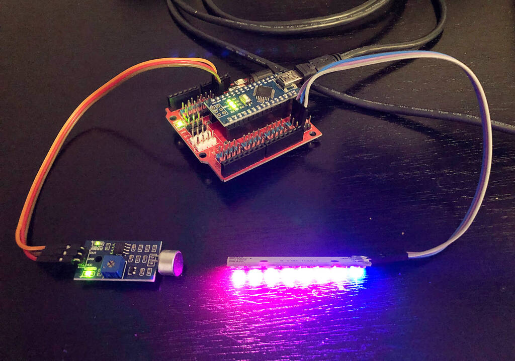
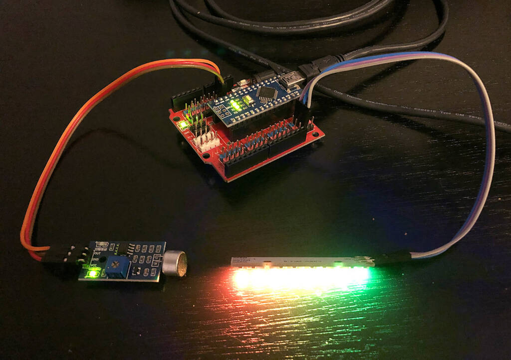
Pictured below: the analog output of a microphone module is used to send a varying signal to a *Nano* microcontroller clone board, which in turn provides varying input to a *NeoPixel* stick.
[](https://www.pinballnews.com/site/wp-content/uploads/learn/pinball-add-on-controller/004-pinball-add-on-controller.jpg)
A microphone module is the input, a NeoPixel stick is the output
From looking at the associated sketch (NeoPixel-Color-Changing-VU-meter.ino – available to [download here](https://pinballnews.com/site/wp-content/uploads/learn/pinball-add-on-controller/NeoPixel-Color-Changing-VU-meter.ino)), you may notice an analog value is: [read](https://www.arduino.cc/reference/en/language/functions/analog-io/analogread/), [mapped](https://www.arduino.cc/reference/en/language/functions/math/map/), and [written](https://www.arduino.cc/reference/en/language/functions/analog-io/analogwrite/).
When changing, the assigned values of the written analog value are used to proved changes to the output device, a *NeoPixel* stick. By only slightly modifying this sketch, the Stick can easily be replaced by a [different](https://learn.adafruit.com/make-it-glow-your-first-neopixel-project/choose-your-pixel-type) *[NeoPixel](https://learn.adafruit.com/make-it-glow-your-first-neopixel-project/choose-your-pixel-type)* [type](https://learn.adafruit.com/make-it-glow-your-first-neopixel-project/choose-your-pixel-type).
A microphone module is shown in the bottom left of the picture above. In this picture, notice the green barely-lit LED in top-left corner of the microphone module. The lighting of this LED signifies audible activity. This activity gets turned into a packet of digital information which is executed by the *NeoPixels*.
Notice in the second picture, below, the green LED at top-left on the microphone module is extinguished; yet the *NeoPixel* strip on the right is holding its execution of color values.
[](https://www.pinballnews.com/site/wp-content/uploads/learn/pinball-add-on-controller/005-pinball-add-on-controller.jpg)
The upper green LED on the microphone module is off, signifying a lack of sound
The extinguishing of this single green LED signifies lack of audible activity, yet all of the *NeoPixels* remain lit. This situation is purposely chosen in the sketch for lighting homemade pinball machine add-ons and toppers.
[](https://www.pinballnews.com/site/wp-content/uploads/learn/pinball-add-on-controller/025-pinball-add-on-controller.mov)
The *Arduino* sketch for this second example shown above follows and can be [downloaded here](https://pinballnews.com/site/wp-content/uploads/learn/pinball-add-on-controller/NeoPixel-Color-Changing-VU-meter.ino). It is commented to list all of the connections and the operation of the sketch itself.
```
//NeoPixel-Color-Changing-VU-meter.ino
/*
* McSpaghetti
* Aug 12, 2017
* www.instagram.com/mcspghetti
* https://github.com/EEPblog/NeoPixel-Color-Changing-VU-meter
*/
#include <Adafruit_NeoPixel.h>
#ifdef __AVR__
#include <avr/power.h>
#endif
#define NUMPIXELS 8
Adafruit_NeoPixel pixels = Adafruit_NeoPixel(NUMPIXELS, 13, NEO_GRB + NEO_KHZ800);
int val;
int color = 0;
bool change = 1;
void setup() {
pixels.begin();
Serial.begin(115200);
}
void loop() {
int analog = analogRead(A0); //connect the Audio Source here, for best results use an OP amp front end.
int scale = 700; //this ultimately sets the sensitivity, basically the high point for the Vumeter
int threshold = 600; //if the signal crosses this point, the VUmeter will change color
int hysterisis = 500; //the hysterisis is necessary, since it determins the reset value before another color change
val = map(analog, 0, scale, 1, NUMPIXELS); //this scales the Audio source to the amount of pixels in our strip
if ((analog > threshold) && (change == 1)) { //this advances to the next color whenever it peaks over the threshold.
Color++;
if (color > 4) {
color = 0;
}
change = 0;
}
if (analog < hysterisis) { //this allows the change of the color for the next peak
change = 1;
}
Serial.print(hysterisis); //debugging stuff, best if used with Serial Plotter (CTRL + SHIFT + L)
Serial.print(" ,"); //beware, that the serial stream runs at 115200 baud
Serial.print(threshold);
Serial.print(" ,");
Serial.print(scale);
Serial.print(" ,");
Serial.println(analog);
for (byte i = 0; i < NUMPIXELS; i++) { //this draws the palette for our strip depending on the color
variable
switch (color) {
case 4:
pixels.setPixelColor(i, map(i, 0, NUMPIXELS, 0, 255), map(i, 0, NUMPIXELS, 160, 0), 0);
break;
case 1:
pixels.setPixelColor(i, map(i, 0, NUMPIXELS, 0, 255), 0, map(i, 0, NUMPIXELS, 255, 0));
break;
case 2:
pixels.setPixelColor(i, 0, map(i, 0, NUMPIXELS, 0, 255), map(i, 0, NUMPIXELS, 255, 0));
break;
case 3:
pixels.setPixelColor(i, map(i, 0, NUMPIXELS, 0, 255), map(i, 0, NUMPIXELS, 255, 0), map(i,
0, NUMPIXELS, 0, 255));
break;
case 0:
pixels.setPixelColor(i, map(i, 0, NUMPIXELS, 0, 255), map(i, 0, NUMPIXELS, 0, 255), map(i,
0, NUMPIXELS, 255, 0));
break;
}
}
for (int i = NUMPIXELS; i > val; i--) { //this then disables the pixels that don't need to be on
pixels.setPixelColor(i, 0, 0, 0);
}
pixels.show(); //here we draw the result onto the actual LED strip
}
```
Though much of what is covered in this article can be used to create your own pinball feature add-on or topper, the final project we will cover is a pinball topper project. That topper is a custom, ‘The Arkenstone’ or ‘Heart of the Mountain’, from *The Hobbit*.
```
"It was a globe with a thousand facets; it shone like silver in the firelight, like water in the sun, like Jon Snow under the stars, like rain upon the Moon!"
THORIN OAKENSHIELD, THE HOBBIT, CHAPTER XII: "INSIDE INFORMATION"
```
This project is the goal of this set of articles, and uses something Pinball News has previously used as an input – a [LDR / 10Kohm](https://www.pinballnews.com/site/2017/01/12/pin-uino/) combination. This combination provides a trigger for either a *Digispark* or a *Nano* clone board, which in turn controls a random pattern going to *NeoPixels*, which finally light up the pinball topper.
By examining the [set-up](https://www.arduino.cc/reference/en/language/structure/sketch/setup/) portion of the associated sketch (NanoNeoPixeLDRSelfCal.ino which you can [download here](https://www.pinballnews.com/site/wp-content/uploads/learn/pinball-add-on-controller/NanoNeoPixeLDRSelfCal.ino)), you can see that after the [states of the NeoPixels](https://learn.adafruit.com/adafruit-neopixel-uberguide/arduino-library-use) are initially set, LRD/resistor combination gets [calibrated](https://assiss.github.io/arduino-zhcn/cn/Tutorial/Calibration.html).
```
void setup() {
strip.begin(); // Initiate Neopixel library
strip.setBrightness(255); // Range = 000 through 255, 40 = Default,
strip.show(); // Initialize all pixels OFF
while (millis() < (calTime)){ // Calibrate during calTime
sensorValue = analogRead (LRDPin);
if (sensorValue > sensorMax){ // Record sensorMax
sensorMax = sensorValue;
}
if (sensorValue < sensorMin){ // Record sensorMin
sensorMin = sensorValue;
}
}
}
```
Because this initialization and calibration has been placed in the setup portion of the sketch, they run each time the microcontroller is powered up. It is this combination of events which makes the topper run automatically.
The mock-up pictured below shows the topper quickly flashing vibrantly when the game is turned on, and then automatically turning off the topper when the game goes dark.
[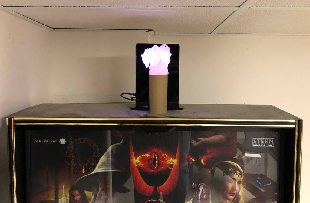](https://www.pinballnews.com/site/wp-content/uploads/learn/pinball-add-on-controller/006-pinball-add-on-controller.jpg)
The Arkenstone topper
If your add-on or topper does not act as expected, the first thing you can adjust in your sketch is the value of:
```
const int threshold = 53
```
See the sketch for notes on adjusting this starting value.
[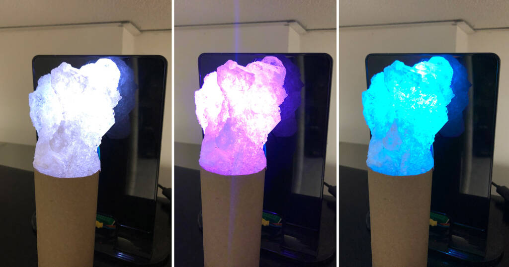](https://www.pinballnews.com/site/wp-content/uploads/learn/pinball-add-on-controller/007-pinball-add-on-controller.jpg)
Shown above are just three of the sparkling colors brightly glowing in ‘the heart’
[](https://www.pinballnews.com/site/wp-content/uploads/learn/pinball-add-on-controller/023-pinball-add-on-controller.mov)
This last *Arduino* sketch, like the others, is commented to list all of the connections and describe the operation of the sketch itself.
```
/*
NanoNeoPixeLDRSelfCal.INO
Todd Andersen
05-NOV-18
Updated for Pinball News
30-SEP-22
*/
// Based on Random Flash Animation
// Random Flash Animation for Neopixel Ring Bangle Bracelet
// by Dano Wall and Becky Stern for Adafruit Industries
// In turn based on the Sparkle Skirt, minus the accelerometer
// https://learn.adafruit.com/neopixel-ring-bangle-bracelet/code
#include <Adafruit_NeoPixel.h>
#define PIXELS 4 // Count of Neopixels on board / strip / ring
#define PIN 1 // Arduino OUT pin for Din pin on Neopixels
const int LRDPin = A1; // Sensor pin = LRD, A1 for Digispark PB2 pin
const int threshold = 53; // Calibrated and mapped sensor trip point for LED display (10 to 100)
// Smaller = More sensative, Larger = Less sensative
const int calTime = 3000; // Time allowed to calibrate trip point (2000 to 3000)
int sensorValue = 0; // Variable to store the value coming from the sensor
int sensorMin = 1023; // Variable to store sensor calibration mimimum
int sensorMax= 0; // Variable to store sensor calibration maximum
int stepMin = 5; // Smaller = Fewer and Larger = Greater
int stepsMax = 20; // Smaller = Fewer and Larger = Greater
int steps = (random(stepMin, stepsMax)); // Set pseudorandom step fade in / out range
int twinkMin = 5; // Smaller = Shorter and Larger = Longer
int twinkMax = 20; // Smaller = Shorter and Larger = Longer
int twinkle = (random(twinkMin, twinkMax)); // Set pseudorandom twinkle time
int pixelMin = 1; // Smaller = Less and Larger = More
int pixelMax = 4; // Smaller = Less and Larger = More
int numPixels = (random(pixelMin, pixelMax)); // Set pseudorandom twinkling number of pixels
// Parameter 1 = number of pixels (PIXELS)
// Parameter 2 = pin number (PIN, most are valid)
// Parameter 3 = pixel type flags, add together as needed:
// NEO_GRB Pixels are wired for GRB bitstream (most NeoPixel products)
// NEO_RGB Pixels are wired for RGB bitstream (v1 FLORA pixels, not v2)
// NEO_KHZ400 400 KHz (classic 'v1' (not v2) FLORA pixels, WS2811 drivers)
// NEO_KHZ800 800 KHz bitstream (most NeoPixel products w/WS2812 LEDs)
Adafruit_NeoPixel strip = Adafruit_NeoPixel(PIXELS, PIN, NEO_RGB);
// Here is where you can put in your favorite colors that will appear!
// just add new {nnn, nnn, nnn}, lines. They will be picked out randomly
// R G B // Use NEO_RGB for NeoLEDs
uint8_t myColors[][3] = { {232, 100, 255}, // purple
{230, 100, 020}, // yellow-red
{255, 000, 000}, // red
{255, 010, 100}, // off-red
};
// Don't edit the line below!
#define FAVCOLORS sizeof (myColors) / 3
void setup() {
strip.begin(); // Initiate Neopixel library
strip.setBrightness(255); // Range = 000 through 255, 40 = Default,
strip.show(); // Initialize all pixels OFF
while (millis() < (calTime)){ // Calibrate during calTime
sensorValue = analogRead (LRDPin);
if (sensorValue > sensorMax){ // Record sensorMax
sensorMax = sensorValue;
}
if (sensorValue < sensorMin){ // Record sensorMin
sensorMin = sensorValue;
}
}
}
void loop() {
sensorValue = analogRead (LRDPin); // Read LDR value
sensorValue = map (sensorValue, sensorMin, sensorMax, 10, 100); // Map calibrated sensorValue
sensorValue = constrain (sensorValue, 10, 100); // Constrain mapped sensorValue
if ((sensorValue) > (threshold)){ // OFF if pinball machine OFF, GI lights = dark
return;
}
flashRandom:(twinkle, numPixels); // First number = 'Wait' delay, Smaller = Shorter twinkle
flashRandom (twinkle, numPixels); // Second number = Number of neopixels to light at one time
flashRandom (twinkle, numPixels);
}
void flashRandom(int wait, uint8_t howmany) {
for(uint16_t i=0; i<howmany; i++) {
// pick a random favorite color!
int c = random(FAVCOLORS);
int red = myColors[c][0];
int green = myColors[c][1];
int blue = myColors[c][2];
// get a random pixel from the list
int j = random(strip.numPixels());
// now we will 'fade in' steps
for (int x=0; x < steps; x++) {
int r = red * (x+1); r /= steps;
int g = green * (x+1); g /= steps;
int b = blue * (x+1); b /= steps;
strip.setPixelColor(j, strip.Color(r, g, b));
strip.show();
delay(wait);
}
// & 'fade out' steps
for (int x=5; x >= 0; x--) {
int r = red * x; r /= steps;
int g = green * x; g /= steps;
int b = blue * x; b /= steps;
// LEDs will be off when done (they are faded to 0)
strip.setPixelColor(j, strip.Color(r, g, b));
strip.show();
delay(wait);
}
}
}
```
All of the sketches in this article are intended for public use, and any of them may be adjusted/modified to fit the user’s needs.
To learn easy ways to marry Arduino *Digispark* and *Nano* clone boards to shields and modules, please see [the first article in this set](https://www.pinballnews.com/site/?p=27423).
**Helpful Links for Going Further**
In addition, here are some extra sketches for the *Digispark* and *Nano* you may find useful in developing your own pinball add-ons.