**Introduction**
Pinball add-ons, mods and toppers are increasingly popular ways to customise your machine, enhancing their appearance or adding features not included by the manufacturer.
While static add-ons can sometimes work perfectly well, creating something which interacts with the gameplay takes things to a whole new level. If, for example, you have an animated toy or additional lighting, how much better would it be if it only activated when the ball is shot into a particular location as opposed to being constantly switched on?
Manufacturers generally don’t want you attaching unofficial mods to their machines and don’t provide an easy way for you to determine the current state of the game, such as when the ball is locked or whether a specific switch has been triggered.
To work out this information and react to it, we need to build our own detection and control system. It sounds complicated, but it doesn’t need to be.
It could be as simple as an additional rollover switch connected to turn on power of the add-on, but these switches are often only activated momentarily as a ball passes over them. Plus, how much better would it be if you could programmatically control one or more add-ons based on the detection of that ball? You could then determine how long an add-on is activated, toggle its state each time the ball is detected, switch on and off multiple add-ons together or in a sequence, and much more.
Creating this kind of interactivity was once a bulky, complicated and costly process, but the availability of cheap, small and modular microcontrollers has changed all that.
Todd Andersen has written previous Pinball News articles describing how to use Arduino Nano clone microcontroller boards along with assorted modules to control various add-ons.
There are many different types of microcontrollers available and just as many different modules which plug in and either sense certain conditions (lights being lit, sounds being made, objects in proximity, etc.) or drive particular devices (light an LED, play a tune, switch on a motor, etc.). These microcontrollers typically only cost a couple of dollars, with the modules often available for under a dollar each.
In his latest articles, Todd firstly describes how to build a simple ball detector using a microcontroller which can activate your chosen add-on, and then shows how that microcontroller can be easily programmed to reliably detect one or more fast-moving balls and active your add-on for as long as you want.
In this example he’ll initially be using an Arduino UNO microcontroller, although UNO clone boards or other types of microcontroller can be used instead and he will [describe some of those](https://www.pinballnews.com/site/2024/02/02/pinball-ball-detector-alternative-microcontrollers/) too.
[](https://www.pinballnews.com/site/wp-content/uploads/learn/pinball-ball-detector/014-pinball-ball-detector.jpg)
The Arduino UNO microcontroller board
Over to Todd.
---
I received two bits of feedback concerning the previous Pinball News two-part article ([Pinball Add-On Controller: Part One](https://www.pinballnews.com/site/2022/12/24/pinball-add-on-controller-part-one/) and [Pinball Add-On Controller: Part Two](https://www.pinballnews.com/site/2022/12/24/pinball-add-on-controller-part-two/)). The first person who gave feedback remarked, “Liked your articles… didn’t understand a word” while the second just stated, “Bit much”.
I hope to rectify my technical overdose with a little simpler and more direct pair of articles.
As before, the first half will concentrate on the hardware while the [second half](https://www.pinballnews.com/site/2024/02/02/pinball-ball-detector-part-two/) will explain how to write the software.
So, let’s get started with hardware.
This itself will be split into two parts: **[Input](#input)** and **[Output](#output)**. Then, two more sections are included: **[Input Tied To Output](#input-tied-to-output)** and **[Installation](#installation)**. Lastly, a **[Hints-n-Tips](#hints-n-tips)** section will close out this Hardware article.
**Input**
We will be using easily-available and affordable infrared (IR) modules for sensing the presence of a pinball.
IR modules use a pair of infrared light senders and receivers. These modules are chosen because they work on the principle of reflectivity to detect an object – bouncing the sender’s IR light beam off the object and then picking it up with the receiver. This makes them work well for sensing the presence of a shinny silver ball.
We will be looking at two types of IR modules here – horizontal and vertical orientation – named according to the direction of the IR sender and receiver.
Here’s an example of a horizontally-orientated IR module.
[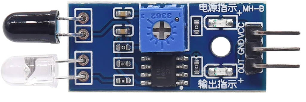](https://www.pinballnews.com/site/wp-content/uploads/learn/pinball-ball-detector/001-pinball-ball-detector.jpg)
Front view of the horizontally-orientated module
Here’s a vertically-orientated module.
[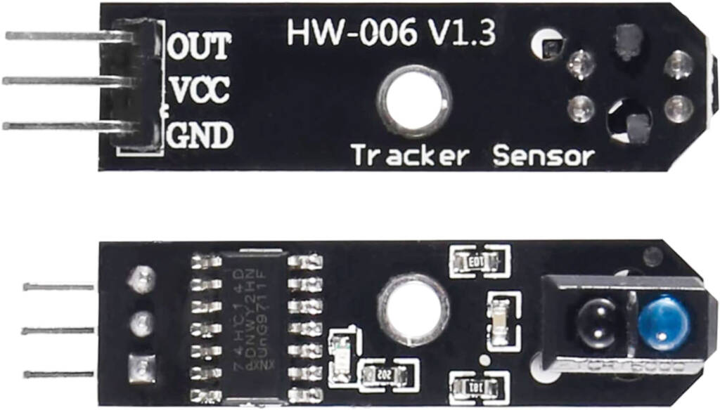](https://www.pinballnews.com/site/wp-content/uploads/learn/pinball-ball-detector/002-pinball-ball-detector.jpg)
Bottom and top views of vertically-orientated module
Notice the lack of a blue sensitivity potentiometer adjuster on this vertically-orientated module.
The main difference between the two types of IR module is the orientation of the [IR sender/receiver pair](https://www.pinballnews.com/site/2022/10/16/new-ir-pinball-testers-part-one/). The pair are located on the right-hand end of the top side on the vertically-orientated module and are quite similar to what was used in another older previous [Pinball News article](https://www.pinballnews.com/learn/irtester.html).
Not all IR modules are quite alike. There is one variation with four pins instead of the three shown above. The extra pin is labelled ‘AO’, but it can simply be ignored for our purposes.
[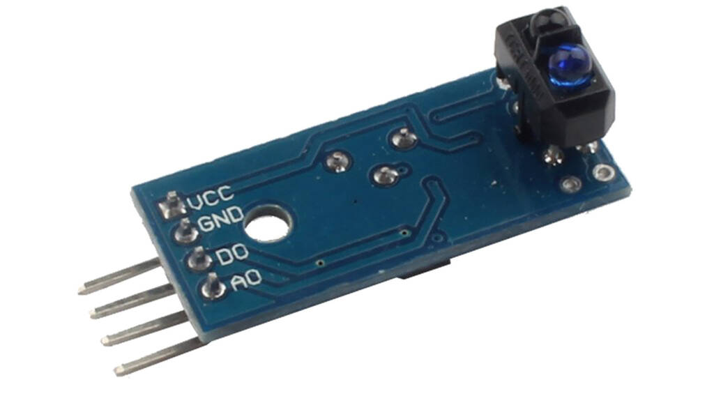](https://www.pinballnews.com/site/wp-content/uploads/learn/pinball-ball-detector/003-pinball-ball-detector.jpg)
A four pin IR module
Speaking of other versions, the connection pins may be labelled differently depending upon the module’s manufacturer. Here are some possible other labels you might find:
| GND **(ground)** | IN **(input)** | OUT **(output)** | VCC **(power)** |
| --- | --- | --- | --- |
| **Bat – Batt – DC – G GD -V Vs Vss** | **DIN S Sig** | **DO** (capital ‘D’ and ‘O’) **DOUT S Sig** | **5V** (or other voltage) **B+ Bat + Batt + DC + P PR PWR +V V+ Vd Vdd** |
**Output**
We will use a different module for controlling the output power – a ‘dumb’ relay module. This is simply a mechanical relay switch which we are using as our output device.
Although this module is powered by five volts, its relay contacts are electrically isolated from the module itself. That means it can be used to switch add-ons or toppers which require a different voltage.
[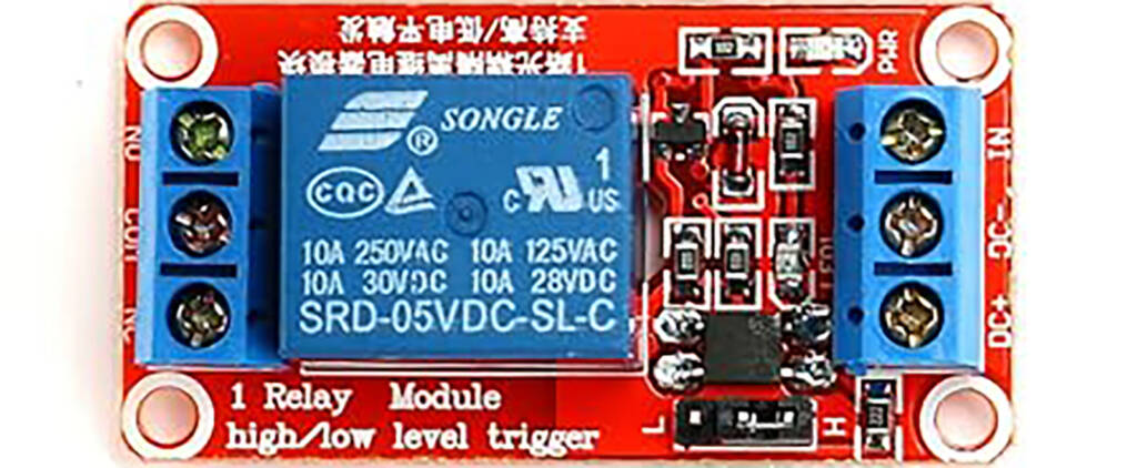](https://www.pinballnews.com/site/wp-content/uploads/learn/pinball-ball-detector/004-pinball-ball-detector.jpg)
A typical relay module
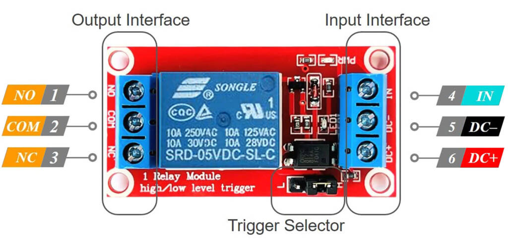
The picture below shows how this relay module is connected.
[](https://www.pinballnews.com/site/wp-content/uploads/learn/pinball-ball-detector/013-pinball-ball-detector.jpg)
Connections to the relay module
The Input Interface is the part which connects to power and the signal from the microcontroller board.
**Input Interface:**
***4* *IN*** is the connection from the output pin of your microcontroller board
***5* *DC-*** is the negative or ground connection of your power supply
***6* *DC+*** is positive connection of your power supply
The Output Interface is the part which provides power to your add-on or topper.
**Output Interface:**
***1* *NO*** is the Normally Open relay contact
***2* *COM*** is the Common relay contact
***3* *NC*** is the Normally Closed relay contact
With unpowered Output Interface connections, this module can be used as a direct replacement for a mechanical switch inside a pinball machine. But **only** with the output connections unpowered! In this case only the Common (COM) and Normally Open (NO) connections are used.
For powered Output Interface connections, there are three relay contacts to consider:
Common (COM), Normally Closed (NC), and Normally Open (NO).
[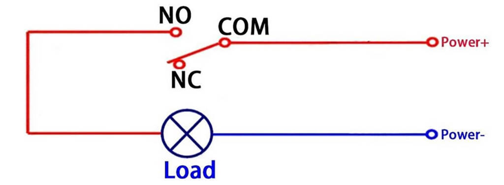](https://www.pinballnews.com/site/wp-content/uploads/learn/pinball-ball-detector/006-pinball-ball-detector.jpg)
Relay wiring when the relay is de-energised
The **COM** connection does not ever change.
The **NC** connection is closed when the relay is de-energised (shown above), and changes to open when the relay is energised.
The **NO** connection is open when the relay is de-energised (shown above) and changes to closed when the relay is energised.
The **Load** in the picture above is your add-on or topper. In our case, the changing of the NO connection is how the Load gets powered.
**Power+** is the positive connection on your power supply and the voltage should be chosen to match the positive voltage required by your add-on or topper.
**Power-** is the negative or ground connection on your power supply.
**Input Tied To Output**
To re-cap, the input is the IR module while the output is the relay module. Tying the two together through an Arduino UNO is what we’ll cover in next section.
First we’ll look at the Arduino’s power and general purpose pins. Then, we’ll see how to use those pins to connect the input and output modules. You can use pre-cut *[Dupont Wires](https://www.pinballnews.com/site/2022/12/24/pinball-add-on-controller-part-one/)* which have suitable connectors already attached to make those connections, or you can make your own connecting cables.
The IR input module has three connections: **VCC**, **GND** and **OUT**.
[](https://www.pinballnews.com/site/wp-content/uploads/learn/pinball-ball-detector/001-pinball-ball-detector.jpg)
The three connections on an IR module
**VCC** goes to the 5V pin on the Arduino board you are using. This is the module’s power source pin.
**GND** connects to the **GND** pin on the Arduino board you are using. This is the module’s ground pin.
**OUT** is the digital signal which goes from the IR module to the Arduino board you are using. For our purpose, many of the Arduino’s pins – Analog A0 through A5 and Digital D0 through D13 – can be used.
[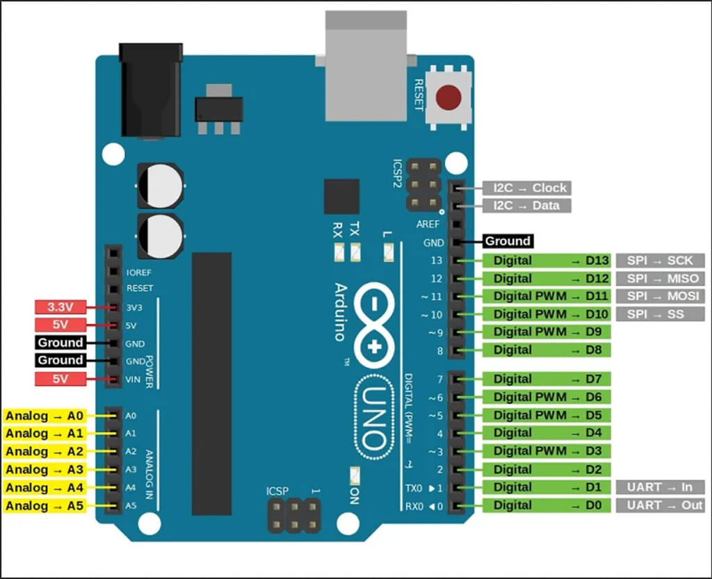](https://www.pinballnews.com/site/wp-content/uploads/learn/pinball-ball-detector/007-pinball-ball-detector.jpg)
The Arduino UNOpins
The Arduino UNO power pins are **3.3V** and **5V**for positive voltage output and **Ground** common connection.
The Arduino has a number of general use pins. These pins are nominally designated as either **Analog** or **Digital**.
**Analog** pins can be used for either analog or digital signals, whereas most **Digital** pins can only be used for digital inputs or outputs.
Inputs receive signals from, in our case, IR modules. Outputs send signals to, in our case, relay modules.
As we will be using the in-built USB connector to communicate with the Arduino UNO, we can ignore all those **grey** secondary labels which relate to an alternative way to communicate with the board.
Arduino [power pins](https://docs.arduino.cc/learn/electronics/power-pins) are just as they sound, pins to which power is connected. There are two types of 5 volt power pins: **5V** and **VIN**.
**5V** is a positive direct current (+5Vdc) supply which is only able to provide a limited amount of power. The power limitation comes from the use of a very small voltage regulator on the Arduino board which can only supply a certain amount of current.
In our case, because we are powering the Uno from a +5V USB power supply, the **VIN** pin is a positive direct current **+5Vdc** source with power mainly limited by the type of USB power supply used. If you were powering the Uno through the board’s dedicated power socket, the **VIN** pin would be connected to that.
It is highly recommended that a power source independent from the pinball machine’s regulated voltages be used to power any add-ons or toppers, such as a high power phone charger plugged into either the games service outlet or an external mains power socket.
**Ground** is the second power connection, and is the return feed from the **VIN** supply to complete the power path.
The picture below shows an IR module, connected to an Arduino UNO, with the same connections we are going to use. Use of these physical connection and the potentiometer will be explained further in the second, software-related half of this article pair.
[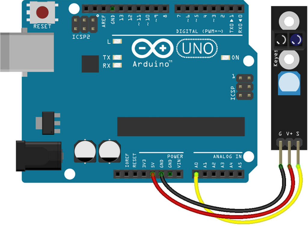](https://www.pinballnews.com/site/wp-content/uploads/learn/pinball-ball-detector/008-pinball-ball-detector.jpg)
A slightly different IR input module wired to Arduino
The Arduino UNO features an LED which is connected to digital pin 13. This can be used to indicate the correct functioning of the Arduino’s programming by showing when that pin is activated.
[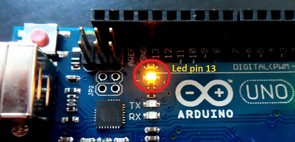](https://www.pinballnews.com/site/wp-content/uploads/learn/pinball-ball-detector/009-pinball-ball-detector.jpg)
The LED on the Arduino UNO’s pin 13
Now we have the inputs and outputs all connected together. Notice the use of in-built LEDs on the Arduino and the modules for power and status indication.
| IR Module | Arduino Uno | Relay Module |
| --- | --- | --- |
| Power LED = **Green** Status LED = **Green** | Power LED = **Green** Status LED = **Yellow** | Power LED = **Green** Status LED = **Red** |
[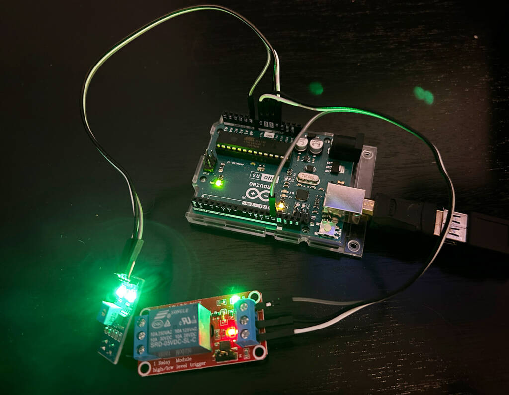](https://www.pinballnews.com/site/wp-content/uploads/learn/pinball-ball-detector/010-pinball-ball-detector.jpg)
The IR input and relay output modules connected to the Arduino
**Installation**
These Arduino modules are very small and can easily fit inside a crowded pinball machine. With a little luck, the machine’s original hardware may be used to Chris Ancarrow them.
Alternatively, a standoff kit could easily be employed to mount the boards properly. These kits are available in several styles and using assorted materials to give a range of colour choices.
[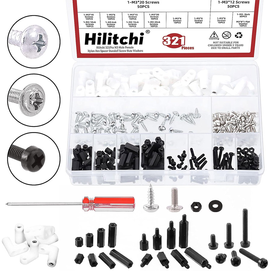](https://www.pinballnews.com/site/wp-content/uploads/learn/pinball-ball-detector/011-pinball-ball-detector.jpg)
A typical standoff kit with lots of mounting options
Hinged standoffs and sticky-backed circuit board mounts are also available in several different sizes and styles.
[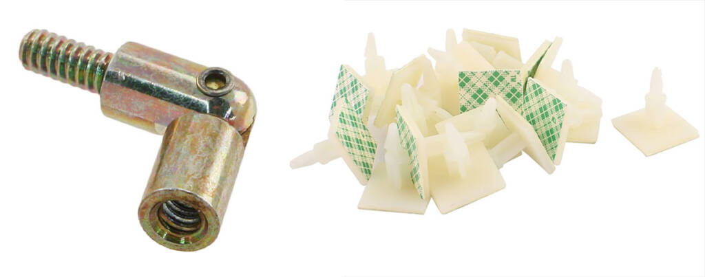](https://www.pinballnews.com/site/wp-content/uploads/learn/pinball-ball-detector/012-pinball-ball-detector.jpg)
Hinged standoff and sticky-backed circuit board mounts
**Hints-n-Tips**
• Above the playfield, the better IR module to use will be the vertically-oriented variety mounted above the point of detection.
• IR input modules with potentiometers are the most versatile.
• Know the type of output you get from your IR input module when the ball is detected (either **HIGH** or **LOW**) and adjust your code accordingly.
• Similarly, verify or set the jumper on your relay output module to the ‘**H**‘ (**HIGH**) or ‘**L**‘ (**LOW**) position.
• Double-check all of your connections before powering your creation for the first time.
• Ensure your creation is not electrically shorting against, or physically binding, anything in your pinball machine.
• Changing ambient lighting, in-game lighting or playfield flashers can sometimes give false signals which trigger the IR module. False triggering can usually be fixed by carefully adjusting the sensitivity potentiometer on the IR module. The vertically-oriented IR module has a built in baffle/beam separator making it physically more immune to the effects of ambient light.
• If your IR input module seems to start acting strangely during gameplay, check how its output/signal indicator LED is behaving. This may be an indication that ambient light is interfering with the sensor, in which case you may need to place a little heat shrink tubing around the bodies of the IR sensor pair. Be sure the lenses/tips aren’t obstructed though.
[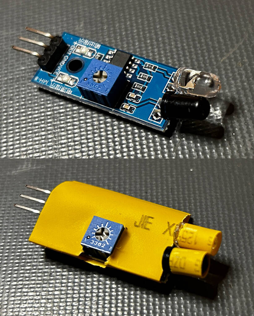](https://www.pinballnews.com/site/wp-content/uploads/learn/pinball-ball-detector/256-pinball-ball-detector.jpg)
Heat shrink tubing around the IR transmitter and receiver, with un-shrunk tubing protecting the module too – The colour of tubing was chosen to make it look as though it were part of the original game
---
In the second part of his article, Todd will show you how to upload some simple software to the Arduino, and describe what each line does so you can modify it to work as you want, or expand it to use additional input or output modules.
[You can click here to view Part Two](https://www.pinballnews.com/site/2024/02/02/pinball-ball-detector-part-two/).